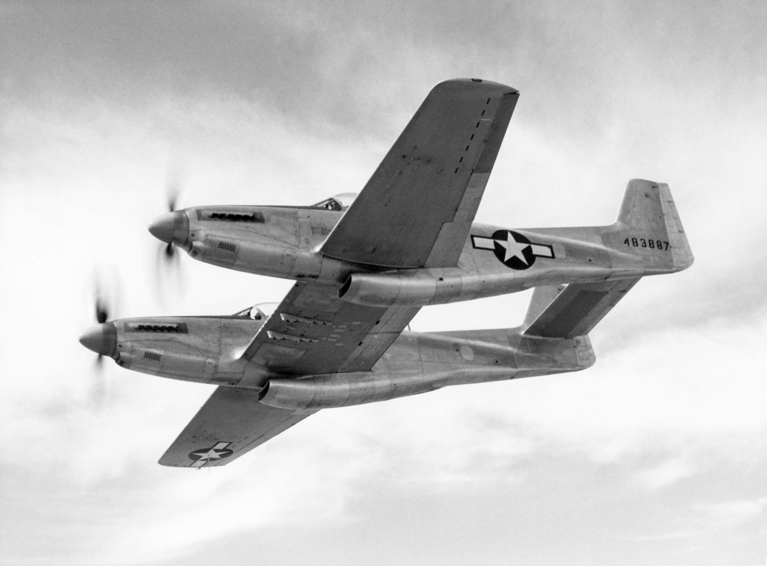
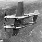
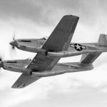
WarbirdsNews has received the latest XP-82 Twin Mustang restoration update from Tom Reilly at his workshop in Douglas, Georgia. Here’s what they’ve been up to this month!
Firewall Forwards
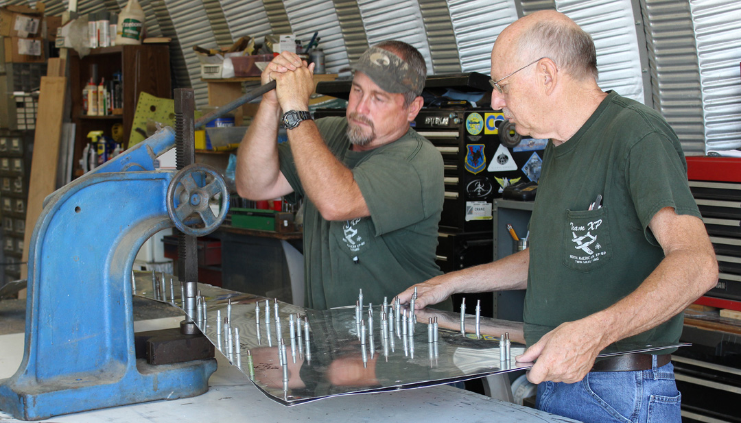
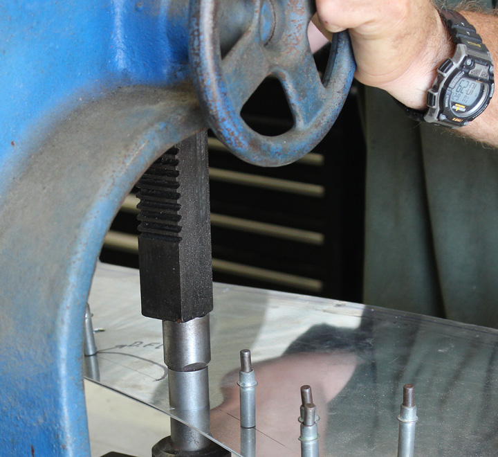
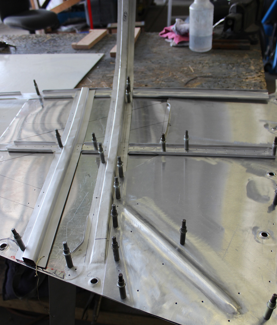
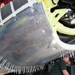
The internal ribbing and reinforcing panels are now completed for the two engine side-cowlings, along with new access doors for the right-hand cowlings. The final microscopic adjustments on the firewall forward, lower cowling ribs to match the English-wheeled lower cowls, on both engines, are now done. The restoration team has also completed the final adjustments on the right-hand engine, upper cowl arches.
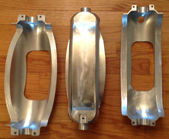
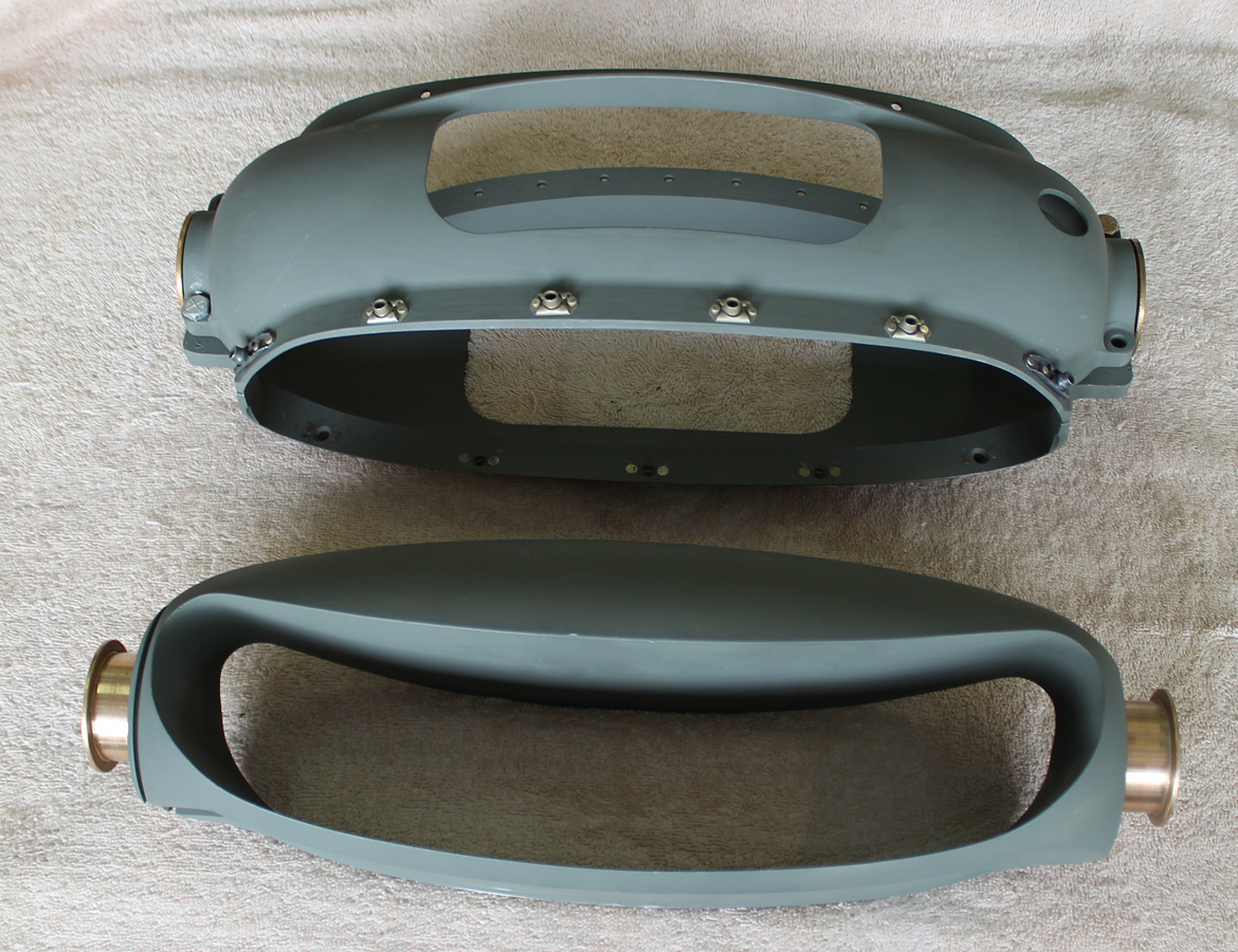
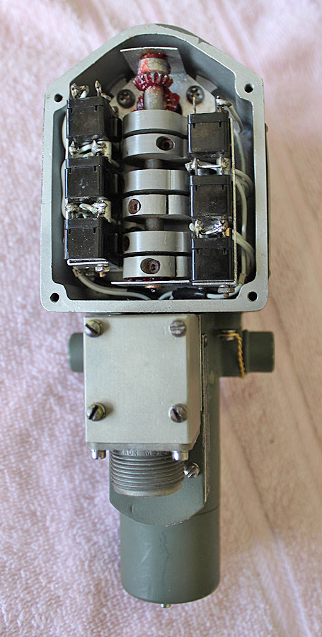
Carb Air Temperature (CAT) Control Motors, Gear Boxes and Rotating Air Control (#1 Ram Air, #2 Hot Air, #3 Half Hot Air and #4 Filtered Air)
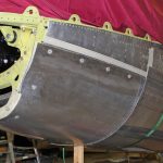
The team has also spent a substantial amount of time installing and adjusting the settings of the rotating cams that actuate limit switches for each stop position on each motor. These pilot-controlled, electrical switches stop the motors at four different carburetor air temperature positions. Also, the original rotating carburetor air control diverter, located under the spinner on the original fuselage, had suffered serious damage due to ground handling and required substantial rework so the internal barrel could rotate. The two shells that hold the barrel were bent, corroded and needed all-new fasteners installed along with the newly-manufactured examples received from one of the project’s contractor machine shops. As you will see from the images below, they did a beautiful job.
Air Intake Scoops
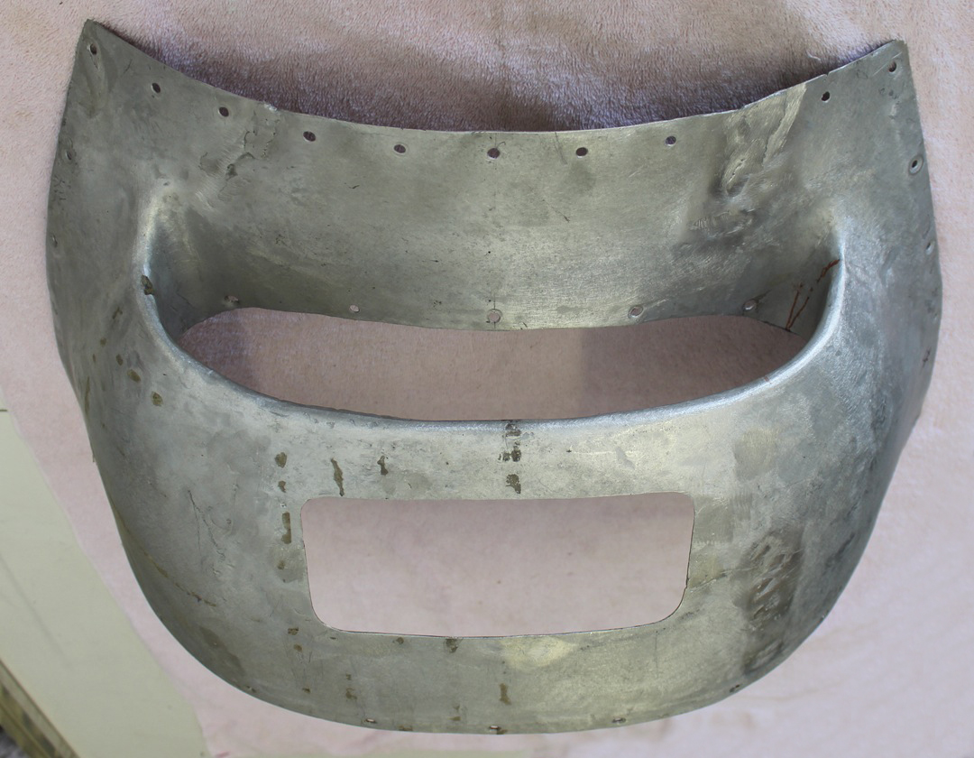
This scoop is located under the propellor spinner and houses the carburetor inlet air control mechanism. This complex, sheet metal component suffered extensive damaged due to ground handling, as previously mentioned. With the acquisition of the newly-manufactured carb air temperature shells that hold the rotating barrel machined perfectly to the original North America Aviation drawings, Tom Reilly’s team was able to make the necessary adjustments to the air intake scoop’s shape so it would fit the cowling and the shells properly. With these final, corrected measurements, Reilly has started making press molds to make two brand-new air intake scoops.
Vertical Stabilizers/Rudders
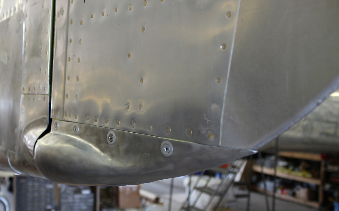
The final 30 degree travel settings to the rudders are complete, and the lower boots are now installed. All four rudder and vertical stabilizer tips are completed through forming and exact bead-welding, as per the originals. Two of the four are now fitted on the left-hand vertical/rudder, and await drilling of the attachment holes.

Armament
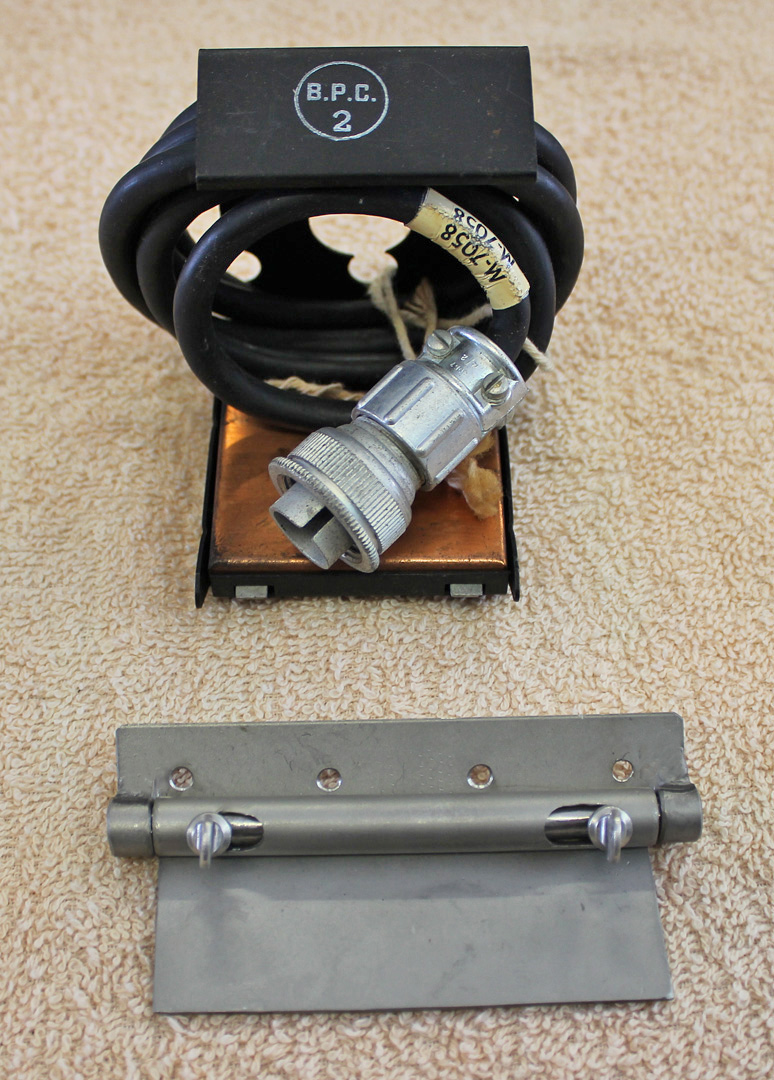
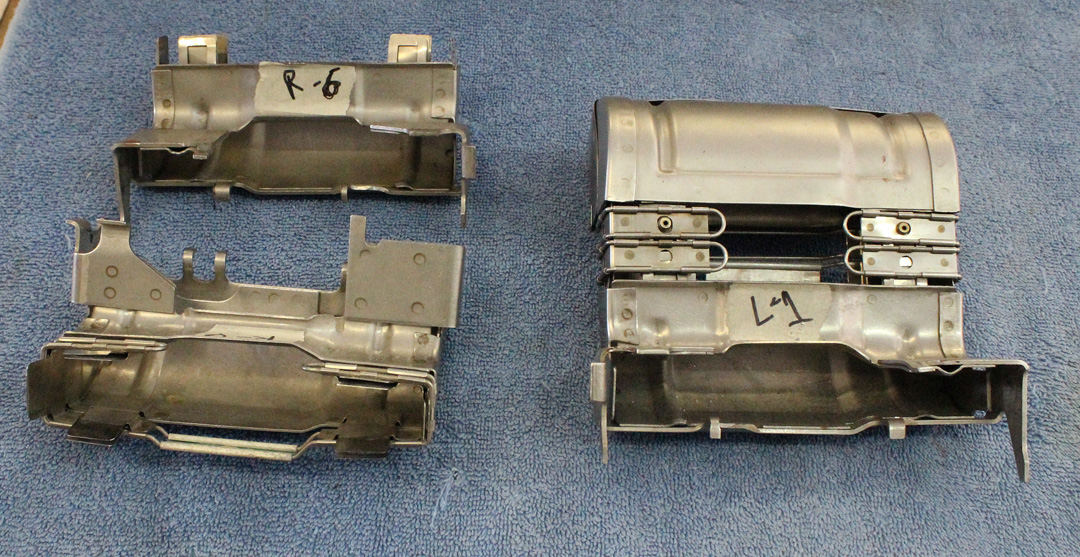
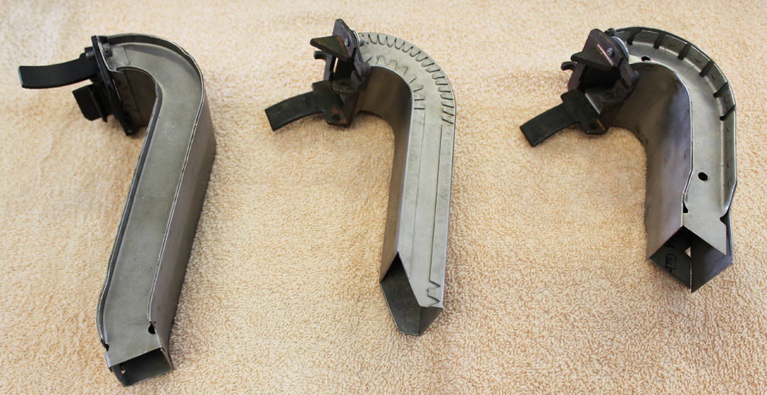
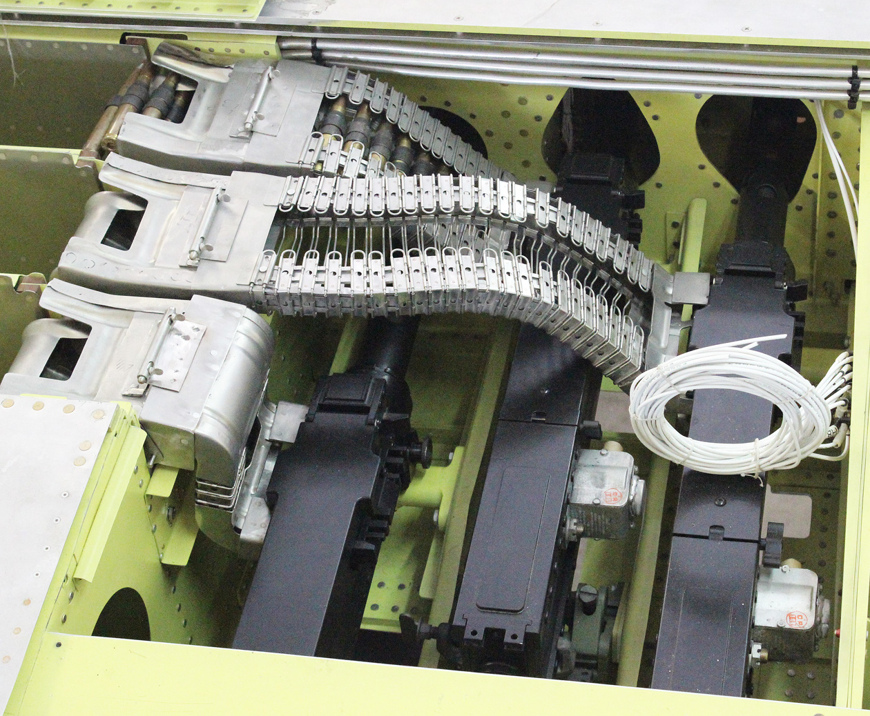
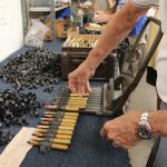
Reilly has had one of his full-time technicians working on the ammunition feed conduits and attachments, from the belting to the ammo boxes, and on the other end to the guns. Welding is now completed for the six stainless steel tubes and spring pins that attach the belts to each ammo feed box. The project has also found a parts supplier, BMG Parts (Browning Machine Gun) in Carson City, Nevada, where they were able to obtain some of the specialized belting and feed chutes that attach to the guns, as well as the stainless steel link ejector chutes and gun heaters. These were all extremely difficult parts to find to ensure authenticity. The few remaining unavailable armament parts can be made in-house.
Firewall Forward Dishpan
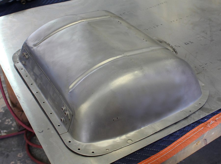
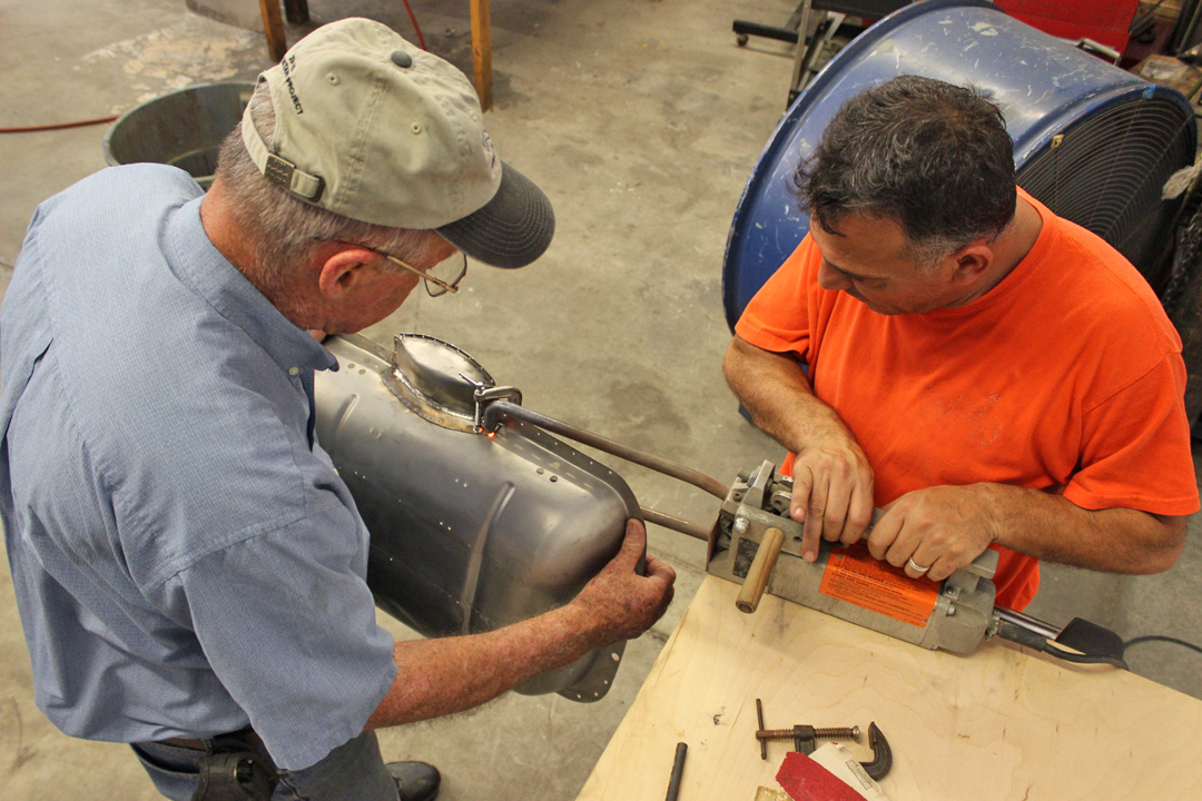
The project was short one oil tank dishpan to complete the right-hand firewall forward. Reilly attempted to draw-form a new, stainless steel dishpan matching the original XP-82 design, but kept coming up with unacceptable wrinkles on the sides. After much studying of the mashed “E” model dishpan that came with the scrap Colorado parts, and with some serious English wheeling and spot welding, Reilly managed to re-form the “E” model pan to match the original XP-82 pan exactly. He had to spot weld an original stainless steel pocket to the bottom of the dishpan shell to accept the 1 1/2” oil-feed supply line from the tank to the engine oil pump.
And that’s all of the news for June, 2016!
———————————-
Many thanks again to Tom Reilly for the update! You can learn more about the project on their blog HERE. Please be sure to check back with WarbirdsNews in August for the next installment in the story following the XP-82′s road to recovery!







I live in Kansas City….I would definitely come to see that thing fly. Please keep me posted.
Will do!