Warbird Digest has just received the February, 2021 report from Chuck Cravens concerning the restoration of the Dakota Territory Air Museum’s P-47D Thunderbolt 42-27609 at AirCorps Aviation in Bemidji, Minnesota. We thought our readers would be very interested to see how the project has progressed since our last article on this important project. So without further ado, here it goes!
Update
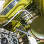
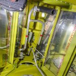
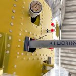
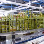
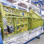
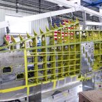
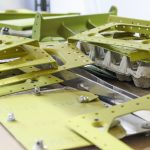
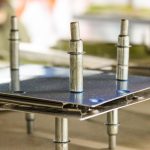
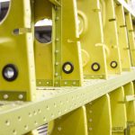
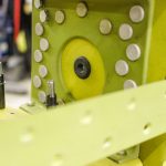
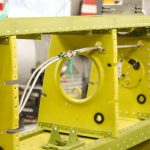
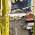
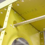
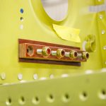
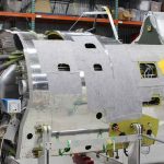
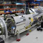
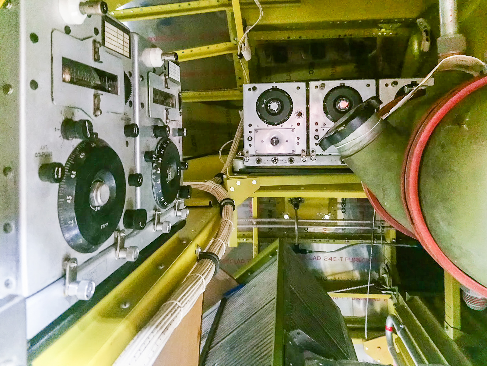
This month, Aaron worked on finishing various custom drain and vent lines unique to P-47s equipped with “Christmas tree” auxiliary fuel tanks. Work also continued on systems within the wings. Meanwhile, the team removed the fitted skins in preparation for permanently riveting them in place.
Finally, we will look into a few P-47 features which are almost unique to the big fighter.
Fuselage
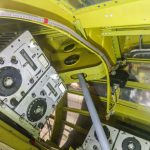
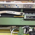
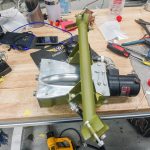
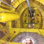
Aaron has finished the main installation of the radio system. He continues work on wiring and hydraulic systems, including some custom routing for Christmas tree tank tubing. He is also installing the oil cooling control system.
Wing
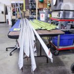
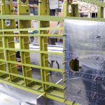
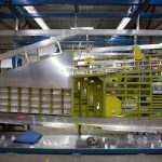
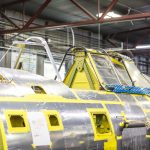
Wherever aluminum skin sections are needed, the newly-made cladding must first be offered up to the structure it will cover for trial fitting and also to match-drill the mounting holes. Once this stage is complete, the technicians will remove the skins in order to debur the holes (sometimes chamfering them), and then they will final-fit the skins against the structure and rivet them permanently in place. This month, the skins are mostly off, but the process of gradually riveting them in place has begun.
Some Unique P-47 Features
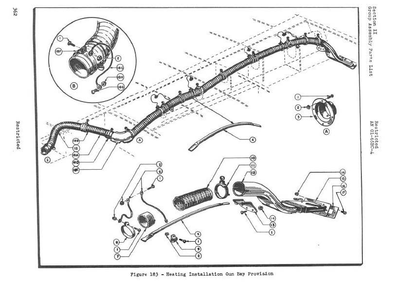
One of the problems engineers had to solve for high altitude fighters like the P-47 was a tendency for guns to become inoperative in the cold air at high altitudes. Lubricants became too thick, any moisture present would freeze; and the result was guns that didn’t fire or fired unreliably. To solve cold related problems the answer is, of course, heat.
The turbosupercharger system made heating the guns with hot air tapped from the exhaust a relatively simple engineering solution.
The Erection and Maintenance Instructions for P-47 Aircraft, page 351 describes the system and the changes that were made as later series Thunderbolts evolved:
“1) The gun bay is heated by hot air tapped off the exhaust manifold tail pipe shrouds at a point just forward of spar 2 of the wings. The air is carried through metal ducts to the gun bay.Systems independent, except for the control knob, are used for each side of the airplane.
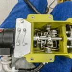
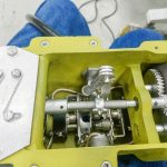
2) Flow of this hot air is controlled by a damper in each duct, located at the point where air is taken from the exhaust shrouds. These dampers extend into the shrouds when open and act as scoops to aid the pressure differential which prevails during flight in maintaining a flow from the shrouds to the gun bays. These dampers are normally open and held by spring pressure. They can be closed and locked by means of tension cables working in flexible casings which run to a control knob located near the trim tab control at the left side of the cockpit. This knob is pulled and turned clockwise to lock the dampers closed.
3) The gun bay heat control assembly was not included in P-47D-15 through P-47D-30 airplanes. On these airplanes the duct dampers are spring loaded to the open position so a constant supply of heat is provided.
4) P-47D-20 and subsequent P-47 airplanes have an additional duct to supply heat to the outboard gun. On P-47D series airplanes, this consists of a separate duct which picks up heat as it enters the gun bay and directs it to the outboard gun. On P-47N airplanes, a “Y” is included in the heating duct; one branch directing heat to the inboard side of the gun bay and the other branch directing heat to the outboard gun.”
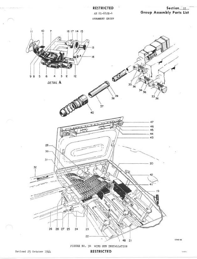
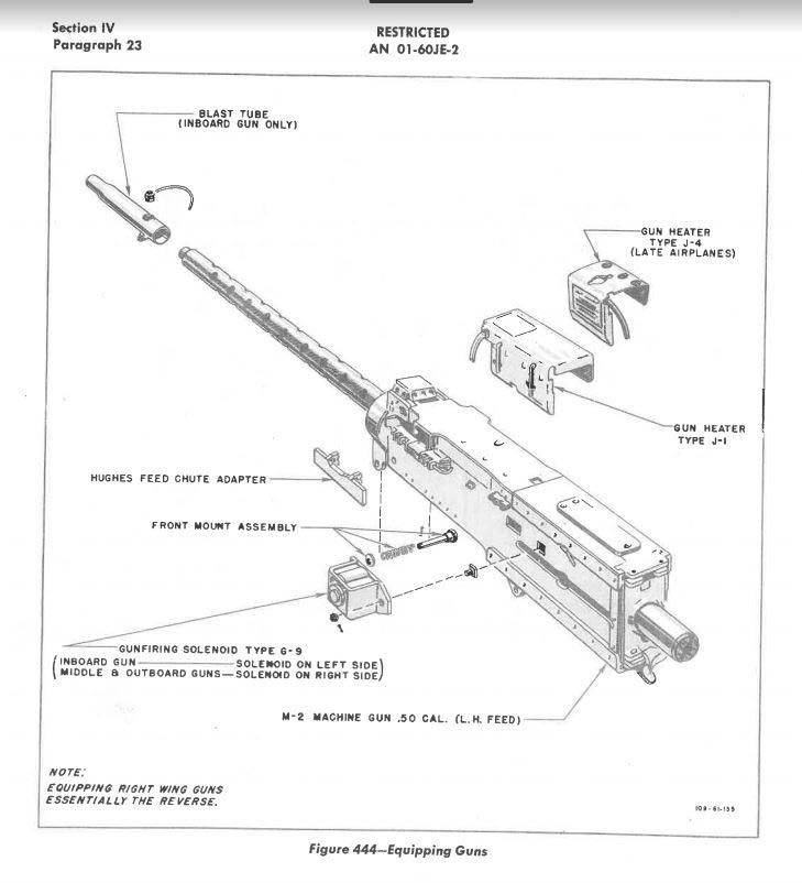
This system is a stark contrast to the P-51 and many other fighters which used electrical gun heat systems as shown in these diagrams from the P-51 Parts manual:
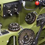
Another difference between the Mustang and Thunderbolt is how the oil temperature was controlled. On a P-47, an oil temperature regulator is controlled manually via electrical switches. From the Pilot Flight Operating Instructions for the P-47:
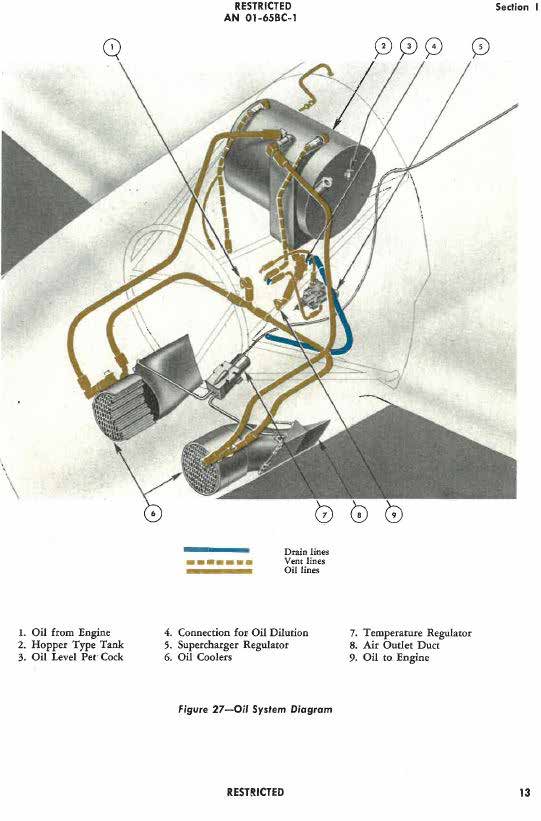
“Oil COOLERS.—- Two oil coolers are installed , one on each side of the lower part of the engine compartment. Adjustable split doors are located in the exit ducts and are electrically operated and controlled from the cockpit by a switch.”
The oil temperature regulator switch location varied, some P-47s had it on the main switch panel, but our D-23 had it mounted near the shutter indicator on the left side of the cockpit.
the location of the oil cooler temperature regulator box assembly (#7).
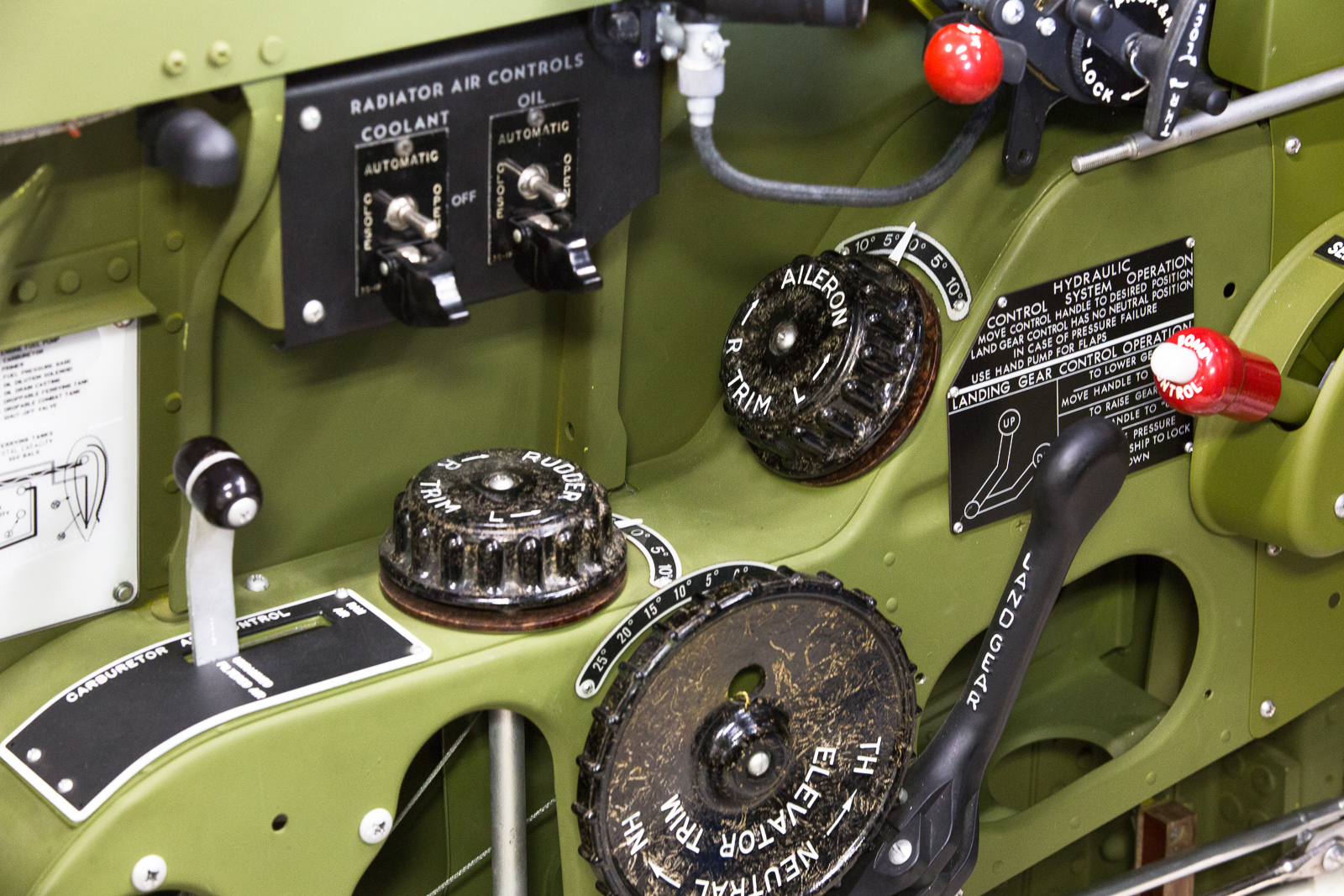
In contrast to the manually controlled oil temperature regulating system on the P-47, the P-51 had a more automated system.
A P-51’s oil temperature is controlled automatically by an electric actuator for the oil radiator air outlet flap. The switch is located on the radiator control panel and has four positions OFF, CLOSE, AUTOMATIC, and OPEN. In normal operation, the switch is left in AUTOMATIC and a thermostat automatically starts and stops the actuator to move the oil radiator air outlet flaps. Only if the automatic feature fails and an abnormal temperature is indicated is it necessary to control the flap manually by changing switch positions between OPEN and CLOSED.
And that’s all for this month. We wish to thank AirCorps Aviation, Chuck Cravens for making this report possible! We look forwards to bringing more restoration reports on progress with this rare machine in the coming months. Be safe, and be well


