Lancaster NX611 ‘Just Jane’ – Restoration Update 173

Richard Mallory Allnutt (Chief Editor)

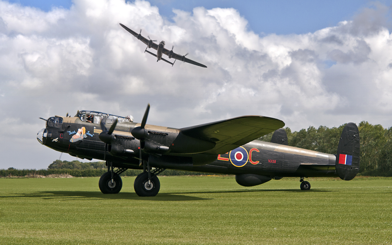
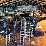
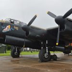
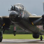
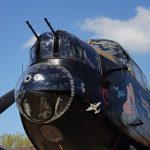
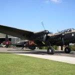
As most of our readers will know, Avro Lancaster B.VII NX611 Just Jane is under restoration to airworthy condition with the Lincoln Aviation Heritage Center at former RAF East Kirkby in Lincolnshire, England. The group has made magnificent progress, even during the pandemic, and we thought that our readers might like to see a recent (edited) report, reproduced here with permission…


The Rivet Club – Newsletter 173

by Andrew Panton

Welcome to Newsletter 173,

This is a bumper edition for June!

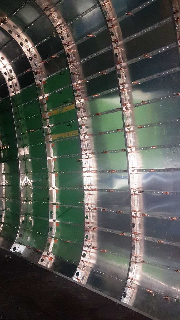
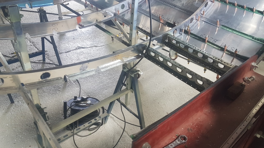
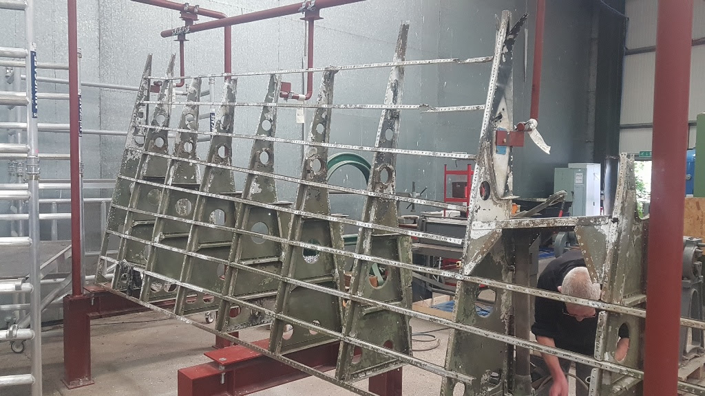
KB976’s rear fuselage has been coming on in leaps and bounds. The formers are now all trimmed, drilled, deburred and permanently fitted into the fuselage. Dave has worked around 60% of the new stringers, de-burring and riveting them together for final-riveting to the skins. Phil has completed his work around the doorway, with all of the reinforcing plates and doubler skins now finished. He has moved on to final-trimming and fitting the stringers located between the transport joint and doorway.

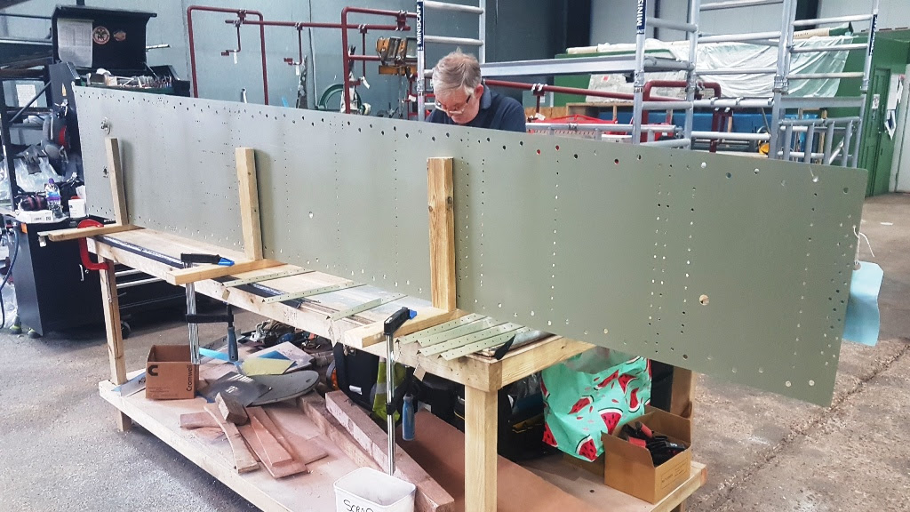
08e1ce47 db46 6c29 6e13 58bf9b81c2df
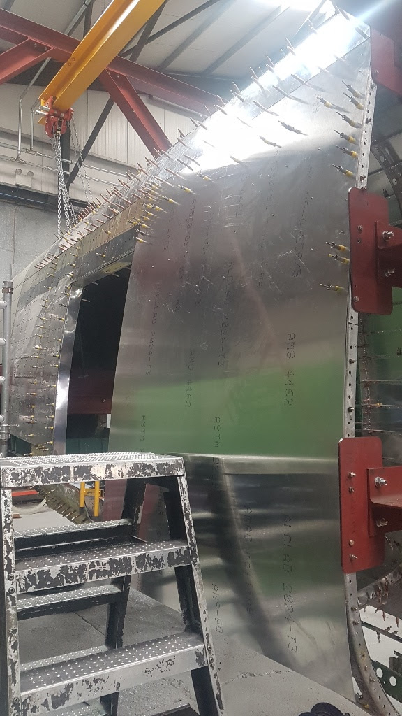
The new side skin for KB976’s rear fuselage. Dave is just beginning to back-drill the holes from the stringers into the new skin.

468a6f1b ce1c d31e 4126 c7268bded36b
The formers and stringers in place on the port side of KB976’s fuselage.

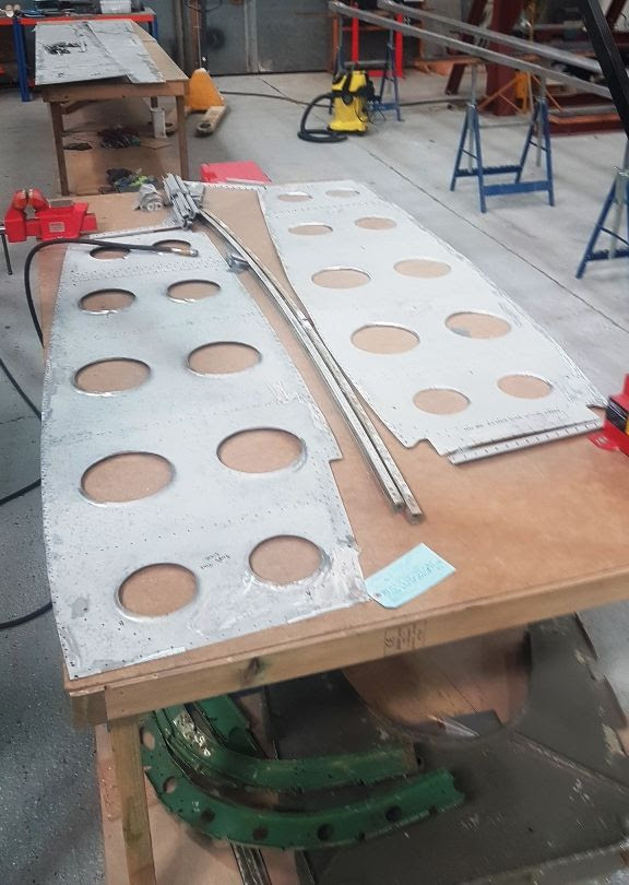
54dd6c98 2690 1e5e d7a8 595f58ed002e
Many of the holes plotted in the skin. The blue skin under the new skin is one the ‘doubler’ skins around the doorway that adds strength where it is lost due to the doorway.

be3702cf 4c77 7bb8 c850 28a89fd2812f
A close up of the skin layout. There is a third skin which also sits over this area as a ‘tripler’.

23cd69ee 13ee 7252 19b9 e9c521d2d2dd
Dave has been progressing through the fuselage stringers riveting the two sections together and then riveting them to the finger brackets where they meet the transport joint.

6286a58a 150f fee7 0644 4a137857b30b
This shows the port side of KB976’s fuselage, with two formers removed to allow the stringers to be removed from the fuselage for riveting.

61972744 a9ac f98a 9405 e8a0f4ffcb12
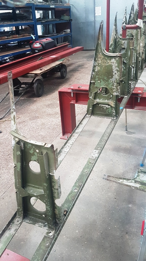
New intercostals for KB976’s fuselage floor are now ready for trimming and drilling.

8a1e975a ea5c 745e 675f 682ac897facd
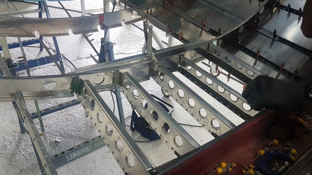
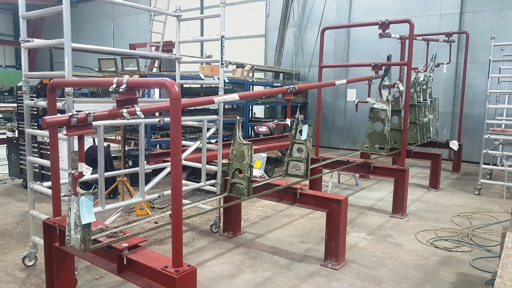
New intercostals fitted to the stringers in the floor area and cut around the finger brackets.  These intercostals not only help strengthen the structure but they also ensure that the formers all have the correct spacing.

4fb32581 dc69 7e37 8ddc 2676c1b4f07e
This shows where the intercostals fit in the fuselage floor.

244a271c e255 fa45 8c1d f4c4f94ef747
New intercostals going in between the transport joint and the first former. The next gap between formers is the start of the downward identification lamp area.

Les has been very busy with the new soda blaster and we have already worked through 1 ton of soda media in cleaning up all of the spar webs, wing ribs and some skins from NX664’s port wing. The blasting is delivering very good results with only the deeper corrosion requiring a final detail finishing with the Roloc discs. This has saved countless labor hours and it is environmentally friendly as well!

[wbn_ads_google_one]

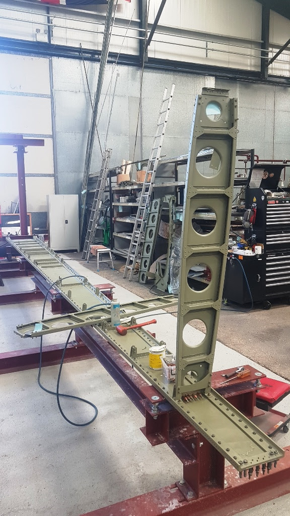
With the spars and webs blasted and now painted, Keith has been able to build the rear spar back up ready for refitting in the jig.  Double-ended studs bolt the spar booms and webs bolt together along their length, but there are also a number of blind rivets employed too, however, we’re still not sure of their purpose! The spar webs are riveted together with joining plates, and of course there are stiffeners riveted to the web plates as well. It’s so good to see the wing going back together now! All of the bolts and studs for the spars/webs have been blasted and cleaned up so they are ready for refitting. We have been able to save the majority of this structure, which is of huge benefit to the project.

3029a00a 6845 d772 f5a3 480bf060459d
The rear spar booms and web for NX664 await being bolted together; you can see that the webs have their stiffeners and rib attachment angles in place already.

408e924e b2da 690e 2b36 7d970921f814
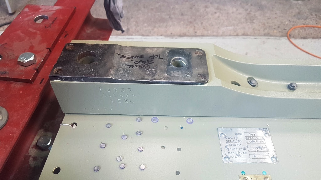
The steel spar plate screwed back in position for the top boom of the rear spar. The bottom boom plate is corroded beyond use, so it will be replaced.

cb049e81 9599 fbe3 a81f da6a771c3136
Keith bolting a boom to the web.  All of the bolts/studs were numbered when removed so that they could be reused in the same holes.

227b4e84 ab93 cb2c 2617 fb17a503f0e7
Keith working his way down the top boom.

ea415045 dd87 fbfa a495 ae232bc7c4e8
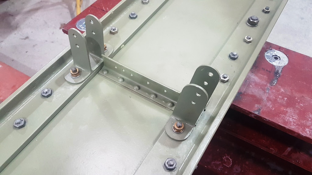
Hundreds of bolts/studs hold the spar booms and webs together. The brackets you can see here hold the wing ribs to the spar.

afdfd19e 4dab 3a79 e0fd 650a482eb6f7
This is the point where the wing ribs attach. They are bolted to the brackets and riveted to the angle piece which in turn is riveted to the spar web.

5abbfe21 1c5e ff06 cd03 487f7e632dea
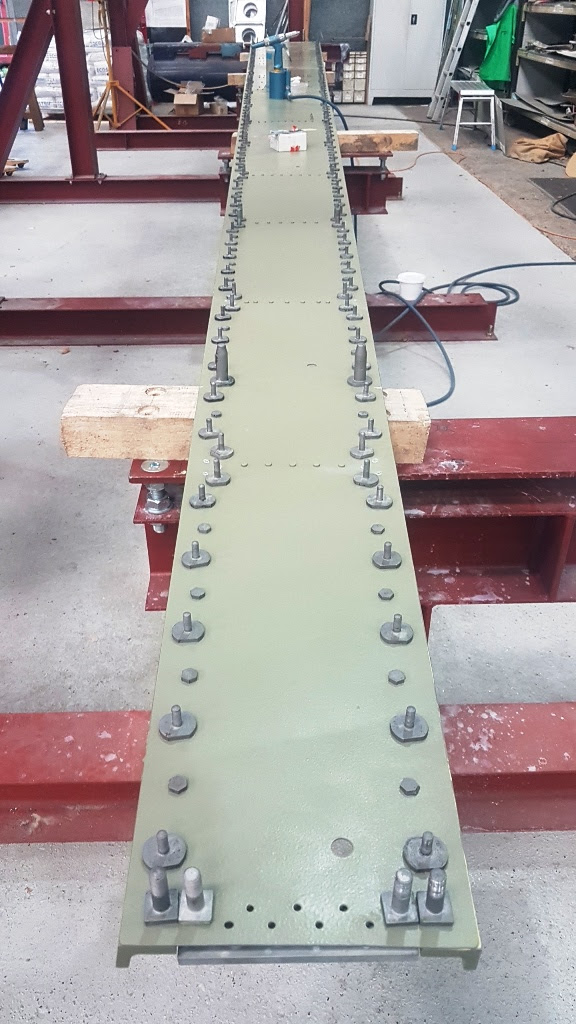
The rear side of the rear spar.  All of these fasteners are attachment studs for the trailing edge.

bf8277e1 0785 0217 8adf 904f793b2c98
At select points along the length of the spar, there are areas of blind rivets.  We don’t really know why they are called for, but it is certainly ‘belts and braces’.

87999f0f 3027 9e71 c20d 802fe7864e57
The part and mod plates for the port wing.

[wbn_ads_google_one]

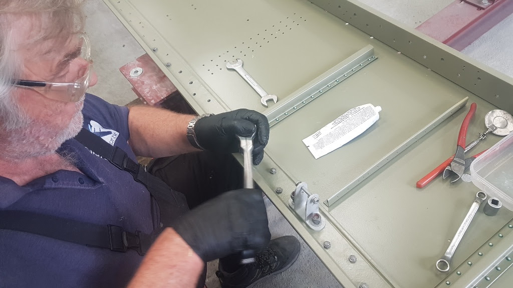
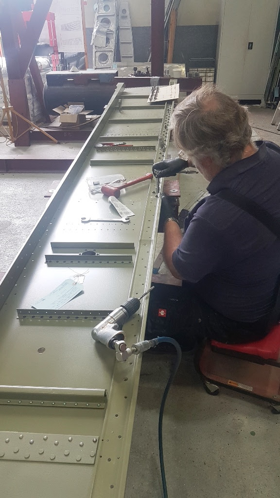
With the wing spars and webs bolted up, Keith has moved on to refitting ribs to the assembly. These components have passed through inspection, blasting and painting prior to this point. The ribs simply bolt to finger brackets which are in turn bolted to the wing spar booms and then riveted to an angle bracket which is riveted to the spar web.

55aebe4b ed58 bb15 03d4 230d386fa231
Some of the wing ribs following soda blasting in preparation for repainting.

2f34b3ca 527b 000d cf44 bbc602ed094e
One of the wing ribs after soda blasting and cleaning with a Roloc disk.

a0b5a482 b233 aee4 b724 4ea58469c265
John drilling out some of the crumbling, magnesium alloy rivets; these are replaced with new rivets, with the assembly then sent for painting.

c296b625 b20e 15ed ebc7 caed7fafcd12
The two wing ribs here have progressed through painting and are now ready for reassembly with the wing.

edbdc4eb 1f8c 1191 a5c1 dce5b471f834
The wing’s end rib wing showing the extruded angle where the wingtip bolts on.

f8c133dc 4805 5f5f ca09 f9fa5203680f
More wing ribs ready for rebolting into the wing.

bfa8dd52 bc81 4a89 0c5a a5c4bf11146d
The wing is beginning to go back together. The first rib is bolted in and just awaiting the rivets to hold the angle to the rib. As is evident when looking down the spar, some of the angles are already riveted to the web and some are off the web and riveted to the rib; it all depends upon which rivets gave way when the parts were dismantled.

f13eb0da cb6f 57ba ff92 549ec00b2b6c
The wing’s end rib ready to receive all of studs which attach the extruded angle to the web.

c3db34cd bee9 b57b e64a 0646031cdbbb
The wing is beginning to look more like a wing again here. The last rib in view is the first of those for the No.3 fuel tank bay. You can see how its shape provides space for the tank.

f554aafb db78 ad9f 4e2f 1ace113f570f
This is the large rib which sits at the wing’s inboard end. It is made up entirely of this U section and fish plates, and is affixed to the wing with large bolts which were difficult to remove during dismantling. The rib is riveted together using special rivets which have to be heated in a kiln for tempering before they can be shot into the structure. This process hardens the rivet, making it stronger.

5038ebf1 3ed2 83e8 0134 ba502f04919e
The first of the webs for the front spar. When this image was captured, the component had come out of the paint shop and was ready to receive its ‘top hat’ reinforcing sections.

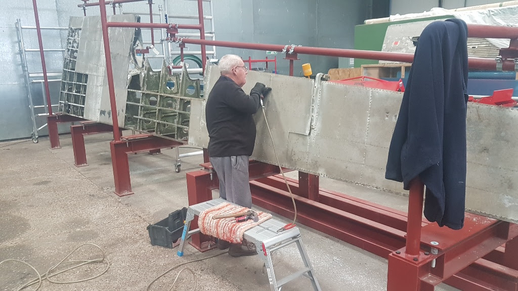
With the trailing edge jig ready for use, Dennis has been able to start stripping the structure apart into its component parts. The remaining skins and stringers have all been removed, as well as some of the ribs. One set of parts which proved difficult to disassemble included the aileron hinge arms, which are bolted through the ribs; these bolts had corroded into the aluminium arms. The normal method for detachinging the aileron is to remove the hinge arms with the aileron as an assembly however,  corrosion has rendered this method impossible. When we refit them, we will hopefully be able to use the method outlined in the manual. Corrosion has unfortunately left the  trailing edge is in a very sorry state!

fc2dfe30 2cf9 3b20 0aab 8b66dbde8170
Dennis removing more skins from the top side of the trailing edge. The aileron attachment hinges are visible. These hinges proved very difficult to remove as the bolts attaching them to the ribs had corroded into the hinges. The bolts, therefore, had to be drilled through down their entire length.

4112fdb6 ef8d 142e 1c9b 2c58bda2557a
More and more skins coming off.

7bf235fb 85f0 c0d1 966d 37b566cca7ec
With the skins removed, you can see quite a few areas of corrosion.

06ece76b 03fe eae9 de86 ec20bd62cc54
Trailing edge ribs undergoing removal. Just like for the main wing structure, these trailing edge ribs are bolted to the spars.

ae8d31e1 a2aa 941c e0a1 4bbea6404578
The trailing edge is almost completely apart in this image. Once removed, all of the structure will undergo cleaning and assessment.

76fa54b5 35d4 339c eea4 28da8a822872
One of the trailing edge ribs.

Our Gofundme Wings Campaign has now reached £34,000 of the 500,000 required! Thank you to everyone who has contributed, as you have helped us to pay for the trailing edge jig. The next goal will be to take the Gofundme campaign to a level that will cover the aluminium sheet metal required for the wings project at a further £6,000.  If you would like to contribute to the Wings Fund and receive your special Wings Fund badge, then please click HERE (badges are sent for donations above the £50)

Stay safe and thanks for your support.

Andrew Panton

[wbn_ads_google_one]


Which aircraft is which?

I have been getting emails double-checking which airframes are which in our hangar, so I have made this list for everyone’s benefit.

Avro Lancaster B.VII NX611: This is ‘Just Jane’ based here at East Kirkby and undergoing restoration to airworthy condition.

Avro Lancaster B.X KB976: This is the rear fuselage section under restoration to taxying condition to fit to NX611 for a year while we restore NX611’s own rear fuselage to airworthy condition. The two components will be swapped once both are complete.

Avro Lancaster B.VII NX664: This is a Lancaster under restoration to static condition in France. We are restoring its wings to taxying condition to swap out with NX611’s, thus enabling us to restore NX611’s to airworthy condition in the interim for eventual swapping back into the airframe.


That’s all for this particular update. We hope that you have enjoyed reading it. As can be seen, a lot of work remains to be done, but the aircraft is well on the way back to flying condition. It is being done in a methodical and careful manner in order to keep the aircraft available for ground-running operations during the summer months. For those interested in helping support this important project, please click HERE

Be sure to check out their store HERE as well… There are many cool items to buy which will help get Just Jane back in the air!

Share This Article
Richard Mallory Allnutt's aviation passion ignited at the 1974 Farnborough Airshow. Raised in 1970s Britain, he was immersed in WWII aviation lore. Moving to Washington DC, he frequented the Smithsonian’s National Air & Space Museum, meeting aviation legends. After grad school, Richard worked for Lockheed-Martin but stayed devoted to aviation, volunteering at museums and honing his photography skills. In 2013, he became the founding editor of Warbirds News, now Vintage Aviation News. With around 800 articles written, he focuses on supporting grassroots aviation groups. Richard values the connections made in the aviation community and is proud to help grow Vintage Aviation News.
4 Comments
  • I take my hat off to you gentlemen, after watching the lanc deteriorate behind our hanger at Blackpool and seeing it being dismantled for transport I am delighted that it is on the way to being airworthy. I hope to visit one day and in the meantime congratulations on what you have done so far and thank you for the excellent video material which no doubt will greatly assist later projects.
    Best Regards. Sam…

  • I am in awe of your progress with this project,your commitment and dedication is beyond remarkable and to have this third Lancaster flying will be an amazing achievement by you all

  • Brilliant stuff!
    I have a question: the “Telegraph” did an article on Just Jane, including a picture [https://www.telegraph.co.uk/content/dam/events/longread/jj.jpg] of an instrument panel.
    At the top right is a shrouded push-button.
    Can you tell me what that button does?
    Why my interest? A half-century ago, I & some friends rebuilt a Land Rover, & drove it from England to Pakistan. We used a button of that type as the starter switch. Hence my interest.

Leave a Reply

Your email address will not be published. Required fields are marked *