B-17G Champaign Lady Update: February 18, 2022
by Scott A. Thompson of Aero Vintage
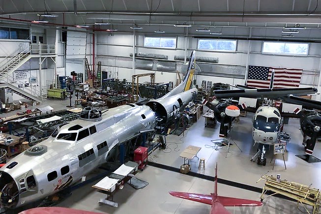
One of the most impressive B-17 restoration efforts presently underway is taking place within the Champaign Aviation Museum’s hangar at Grimes Field in Urbana, Ohio. While the airframe is listed in the books as belonging to B-17G 44-85813, it actually incorporates parts from several different B-17s. Jerry Shiffer initiated this project in 2005, but tragically he lost his life in an aviation accident shortly after the restoration began. His family decided to continue the project in his honor, and so some seventeen years later, an almost fully-restored Flying Fortress fuselage is sitting in the hangar at Grimes Field. This B-17 is now known as Champaign Lady.
The aircraft’s fore and aft fuselage sections are essentially complete, but remain split at the production break located at Station 6 (just aft of the radio room). Numerous other components for the Fort’, such as the horizontal stabilizers, control surfaces, engine nacelles and wing sections, are stored around the hangar.
Dave Shiffer provided a status update for Champaign Lady, including some images of the work currently underway as we move into the spring of 2022.
The work is presently focused upon the B-17’s wings, which consist of three primary components on each side: the inner wing panel, outer wing panel, and wing tip. Two key obstacles to overcome in this endeavor include the obvious scarcity of parts and the FAA airworthiness directive (AD) regarding the spar attachment points which join the wings to the fuselage center section.
Wings: The effort to restore Champaign Lady’s wings has been underway for over a decade, although it is still far from completion.
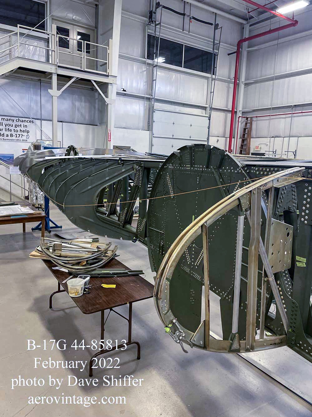
Wing Tips: The two wing tips are of relatively simple construction and small size; the team has already completed their rebuild of these components and they are ready for installation.
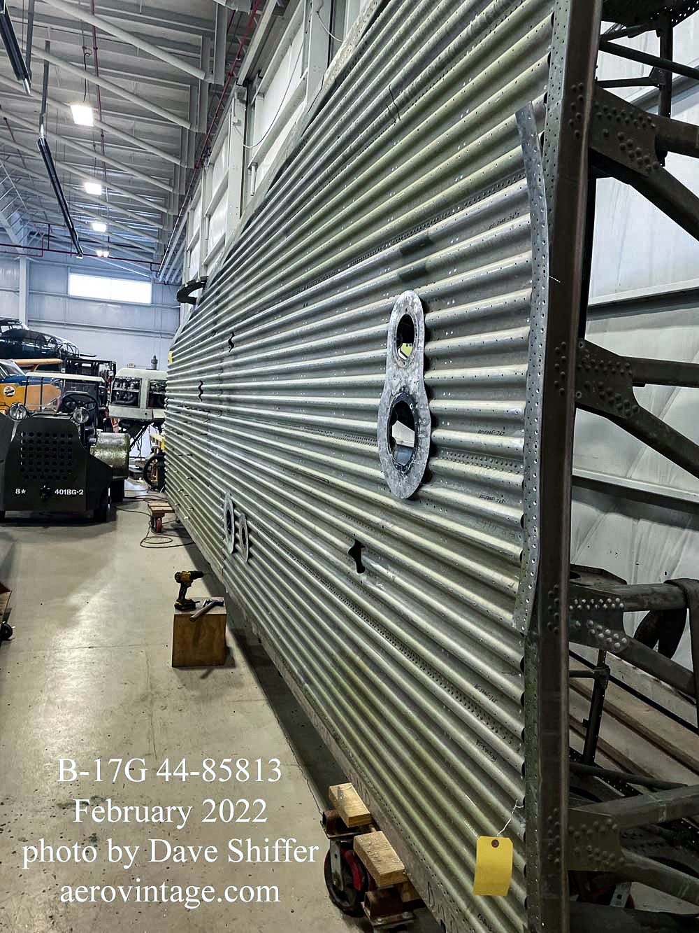
Outboard Wing Panels: The two outboard wing sections came from B-17G 44-83722 which has a history of its own (which I won’t document here). It was last used as a nuclear test target during the 1950s; subsequently the airframe became a parts source for other B-17s. The restoration team disassembled these outer wing panels then cleaned, inspected, and repaired the parts as necessary. Both panels are now under reassembly, being re-skinned with new aluminum. One of the challenges in this process lies with the corrugated subcutaneous layer which greatly adds to the beefiness of a B-17’s wing. Sections of this corrugation have required replacement, with the museum having to custom-press new material.
Inner Wing Panels: A B-17’s inner wing panels include the four engine mounts, the landing gear assemblies, flap attach points, fuel and oil tanks, along with the supporting systems and wiring. Both inner wing panels in this project come from the original 44-85813. Presently the left wing’s inner panel is undergoing inspection to determine how much work is needed for its airworthy rebuild.
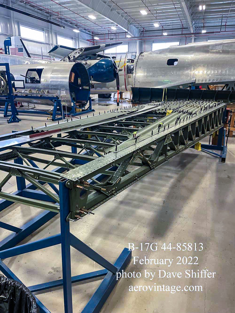
Work on the right inner wing panel, however, has been underway for a decade, with great progress already achieved. The restoration team disassembled this section down to its smallest component parts and then custom-built a precision jig to hold the wing correctly as its reassembly took place.
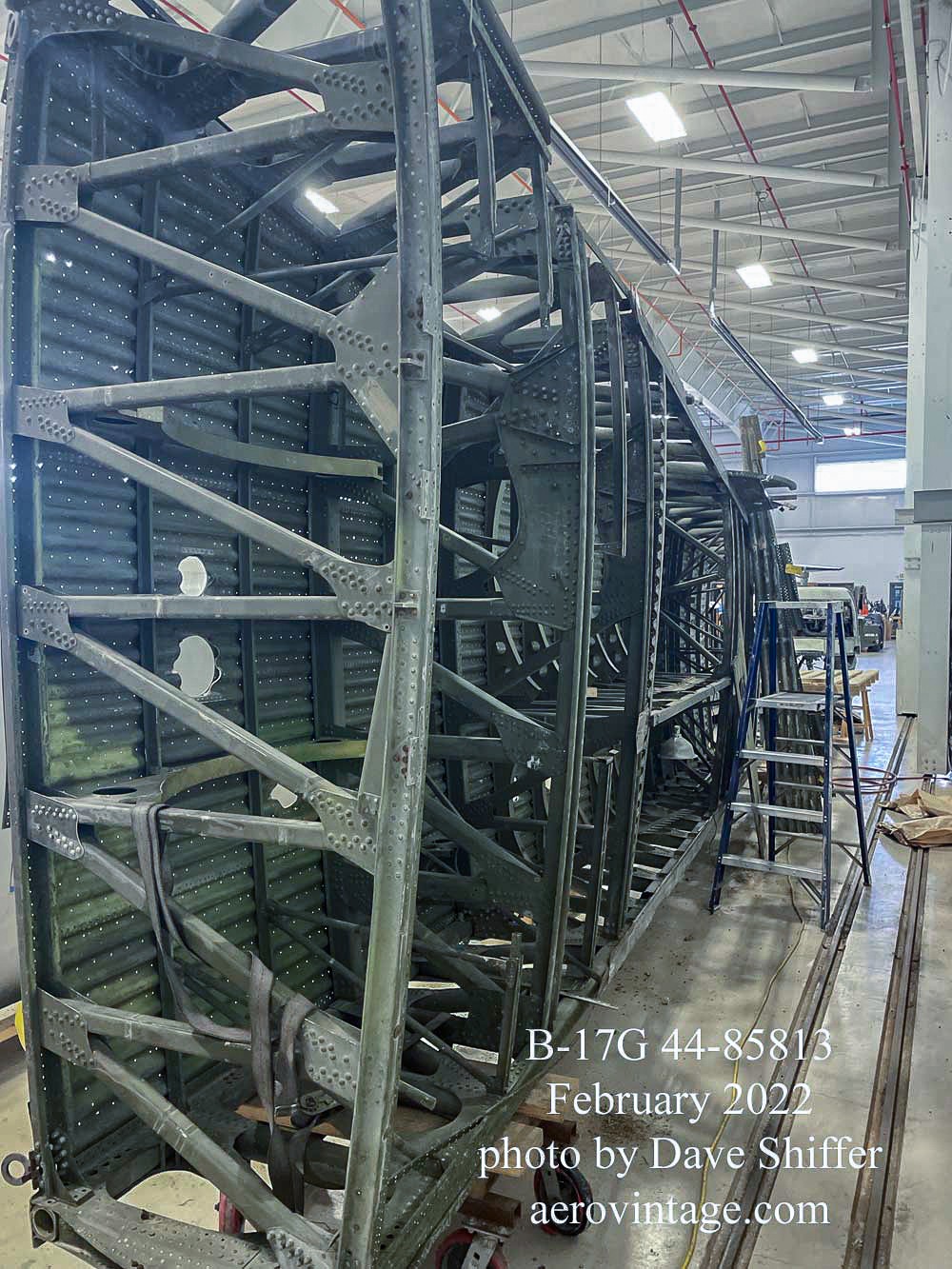
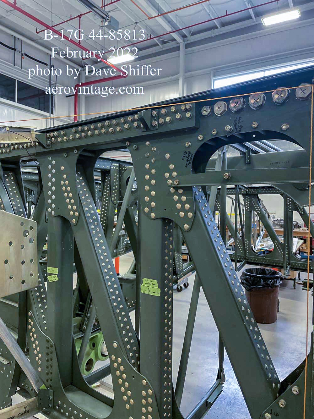
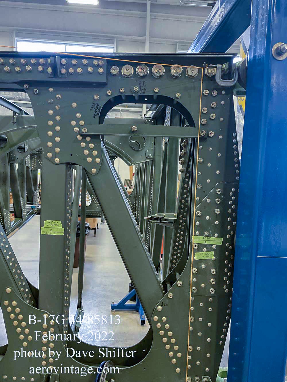
Two truss-type wing spars, forward and rear, form the primary structure for a B-17’s inner wing panel. Each of these spars consists of two spar chords, upper and lower, which are assembled with tubular members to create N-type trusses. The upper and lower spars, both front and rear, are themselves attached to the fuselage center section via steel terminal fittings which are bolted into the inner end of the spar chords. These terminal fittings attach to matching fittings within the fuselage center section and held together with specialized taper pins. Thus, there are four main attachment points which hold each wing to the fuselage, along with two other specialized secondary attachment points located between the upper and lower spars.
The spar chords were originally manufactured as an extrusion. The challenging feature for these spar chords is that they taper down from the wing root for the length of the section, and this taper is both outside and inside the hollow square tubular chord. Many smart people have since tried to figure out exactly how this was done back in the 1940s, but the process to extrude these parts in the exact dimensions as required to match the Boeing design is apparently no longer available; that machining capability is long gone. This is why the inner wing sections are now so rare… original spar chords are needed to build up a wing and there are few undamaged components available. Trying to re-engineer a new wing spar chord using modern components would require a massive effort and re-certification with the FAA, and this would be prohibitively expensive, not to mention time-consuming. It is left to restorers, therefore, to use the original Boeing specifications for construction and repairs to the wing structure.
The other problem with a B-17’s inner wing involves the steel terminal fittings where each of the four spar chords connect to the fuselage center section. Each of the four attachment fittings slides into its respective spar chord and is held precisely in position by eight close-tolerance bolts. Back in 2002, inspections revealed that these spar chords and steel attachment fittings were subject to cracking around the holes drilled to hold the bolts. This discovery prompted an FAA Airworthiness Directive (AD) which requires close inspection of these components to find and repair any cracking. The AD offers several methods of compliance for these inspections, but if cracking is found, then repairs are obviously required; the FAA must approve any procedure to make these repairs. (The text and comments on the 2001 AD make for interesting reading, at least for some B-17 aficionados.)
This brings us to the work on Champaign Lady’s right inner wing panel. As part of the rebuilding process, each of the spar chords received close inspection, both inside and out. The interior inspection involves the laborious process of snaking a camera within the entire length of the chord, checking each surface. Unfortunately, this inspection revealed cracking in the areas of the steel terminal fittings on three of the four attachment points. The damage was fixable, however, and the repairs were made, with FAA input, in precise accordance to Boeing’s instructions as contained in the wartime AAF Technical Order on Structural Repairs for the B-17G. Essentially, the restoration team removed the damaged sections and replaced them with new extrusion material. These new sections were spliced in with a solid inner core extending, as specified, beyond each end of the gap, with external plates added fore and aft to the spar chord. Holes were carefully drilled and bolts added to hold the entire assembly together.
That work is now complete for the right inner panel, with the truss spars now assembled in the jig. In the past months, the ribs and stiffeners have been assembled, with the nose ribs presently being attached to form the wing’s leading edge. Interior fittings to hold the fuel tanks and other components have also been assembled. Nacelles for the number three and four engines were completed separately and are ready for adding to the wing panel at the appropriate time. The major assembly to attach the right main landing gear has also been fitted into the area aft of where the number three nacelle will be installed.
As the images reveal, building up a B-17 wing is no easy task; it has taken many years of dedicated work from a talented team to bring the restoration to this point. Indeed, Champaign Lady’s wing team has become expert in the art of repairing spar chords and terminal fittings. This is a good thing, because an inspection of the left inner wing panel has revealed that at least one of the four spar chords and terminal fittings will require similar repairs.
Any readers wishing to see further details regarding this aircraft’s restoration should search YouTube with the terms “Champaign Lady B-17”. There are a variety of short videos, such as this one, which document different phases of the rebuilding effort. Be sure to check out the Champaign Aviation Museum’s website as well. Donations to their efforts are cheerfully accepted, by the way, as detailed on their website.
And finally, I would be remiss if I did not mention that the B-17’s post-war story in both military and civil use, along with the complete history of B-17G 44-85813 and the 47 other surviving Flying Fortresses, is told in words and pictures within my book Final Cut: The Post-War B-17 Flying Fortress and Survivors
Many thanks indeed to Scott A. Thompson (and Dave Shiffer) for allowing us to reproduce this article (with slight edits) describing Champaign Lady’s present condition… his book, Final Cut: The Post-War B-17 Flying Fortress and Survivors is the gold standard when it comes to the airframe history it describes!


