As most readers will be well aware, AirCorps Aviation has completed numerous world-class aircraft restorations over the past decade or so at their now-famed workshop in Bemidji, Minnesota. They are working on several different projects at present, with one of these being the rare P-51B Mustang known as Shillelagh, which they are rebuilding for the Dakota Territory Air Museum. Chuck Cravens has provided us with several updates on this marvelous project over the past few years, and this is his latest. We feel sure that our readers will enjoy learning what the master-mechanics at AirCorps Aviation have been up to since our last report in February 2025.

Overview:
In recent weeks, the restoration team has made progress fitting systems into the Mustang’s fuselage. These include items for the controls along with electrical and hydraulics installations, which always consume a lot of effort on a restoration like this one. AirCorps Aviation has also advanced the wing rebuild, its structural framework coming together nicely.
Fuselage:
Regarding the fuselage, the restoration team has focused on the hydraulic systems, engine control pedestal, and flight control cables in recent weeks.


ready to install. (image via AirCorps Aviation)


Wings
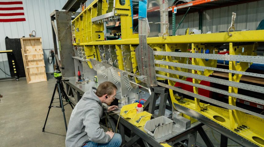
The restoration team has worked hard on the wings, which are becoming ever more complete as structural members like ribs and support stringers are added to the assemblies in the fixture.


Comparing the P-51B/C and P-51D/K Wings:

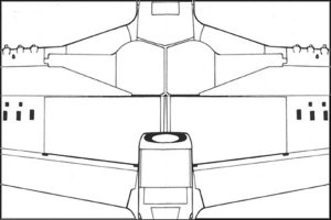
The two illustrations below reveal some of the notable external differences between the B/C and D/K variants of the P-51 Mustang. Notice the difference in wing root styles. The D/K model has a longer root chord and slightly different gear doors which necessitate a more pronounced “kink” in the leading edge. The landing gear uplocks are also different between B/C and D/K Mustangs. Furthermore, there are just four gun ports and spent cartridge ejection ports on the B/C wing, while there are six of the same on the D/K wings.
The following images show the completed wing and gun installations for Lope’s Hope 3rd, one of Dakota Territory Air Museum’s other B/C model Mustangs.


 The Browning M2 machine guns were mounted at a slant in B/C Mustangs. (Scott Slocum image via AirCorps Aviation)
While the B/C Mustang variants featured only two guns per wing and the D/K models had three, the dimensions of the gun bay itself were the same. North American was able to fit three upright M2s in the same space as the two slanted mount .50 calibers, only needing to change the holes through the spar and leading edge to accommodate three guns instead of two. There is a myth which surfaces periodically that North American adjusted the wing thickness for the D/K model to accommodate the upright machine guns, but this is not the case. The airfoil and wing thickness for all Mustangs from the prototype NA-73 through the last P-51D-30NA produced had the same wing other than the altered “kink” at the root. The experimental XP-51F, XP-51G, P-51H, and twin Mustangs had a different wing design.1
¹ Robert Gruenhagen, Mustang , the Story of the P-51 Fighter, Arco Publishing, N.Y., N.Y, 1969,1976 The two-gun-per-wing ammunition bay of a B/C Mustang had two feed chutes and narrower
ammunition bay doors than the D model with its three guns per wing. (Scott Slocum photo via AirCorps Aviation)
Legendary Mustang ace, Brigadier General Clarence ‘Bud’ Anderson commented on the Mustang’s armament during an interview at EAA AirVenture Oshkosh some years ago, stating: “Initially, P-51Bs had problems with gun jams. We learned that the guns had to be absolutely clean and not oiled, as the oil could freeze at altitude. Another problem with the B model guns was that they were mounted on a slant in the wing, which could cause a gun to jam. The P-51D fixed that problem by having the guns mounted vertically. Our P-51B’s normal load was 350 rounds for inboard guns and 280 rounds for outboard guns. The P-51D held 400 rounds for each of the two outboard guns and 270 rounds for the center and inboard guns.”
North American worked on this problem, publishing its solution in Technical order 01-60JD-44 (see below), which included a modification to the ammunition feed chutes and belt holding pawls. This cured the jamming issue.
And that is all for Chuck Craven’s latest update on AirCorps Aviation’s restoration of P-51B Mustang Shillelagh. We look forwards to hearing more in the near future! Many thanks to Chuck Cravens and especially to AirCorps Aviation for their continued, long-standing support!





![Interview with Eric Trueblood, Co-Founder of Aircorps Aviation [VIDEO] 14 Copy of Copy of Copy of Copy of P 47 Thunderbolt](https://vintageaviationnews.com/wp-content/uploads/Copy-of-Copy-of-Copy-of-Copy-of-P-47-Thunderbolt-150x150.png)
